Introduction
This is the second in a series of two labs introducing you to building and programming your own robot. In this lab, we’ll extend the functionality of your robot by adding sensors, allowing it to interact with its environment. You’ll start by integrating photoresistors to guide your robot toward the brightest 🌟 light 🌟.
Then, you’ll choose another sensor to give your robot additional behaviors, such as obstacle avoidance or wall following. By the end of the lab, your robot will sense and adapt to its surroundings autonomously.
🦺 Safety & Important Tips
(1 minute read)
- Unpower your circuit when making any change
- Double check your wiring before plugging in
- Watch for solder bridges
- Components can be fragile—treat them carefully
🔨 Fabrication Quest of the Day
Today, you will use sensors to do closed-loop control of your robotic car:
- Understand how to read values from various sensors with your Arduino
- Use photoresistors to guide the robot toward light
- Implement a new behavior using an additional sensor
🏗️ Software & Hardware
Software: Arduino IDE
Hardware: Assembled Mr. Roboto from previous lab, Ultrasonic Sensor + Bracket, Jumper Wires, Photoresistors (3x), 10kΩ Resistors (3x), Flashlight (x1), Misc sensors for Remix (color, IMU, ultrasonic etc.)
Machines: Soldering Iron
Part 1: Reading Values from Photoresistors (A0–A2 Setup)
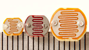
We’ll start with the simplest sensor: the photoresistor. It allows us to measure brightness and guide our robot toward light. ⚠️ Unplug your Arduino before breadboarding ⚠️
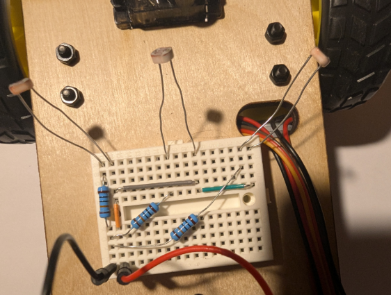
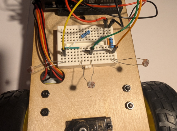
- Add 2 resistors and photoresistors pair, wiring to A1 and A2. Ensure you have spaced them out and
angled them slightly forward. Refer to images below
- Adjust the following code to print the new values. How consistent are the values between each photoresistor?"
#include <AFMotor.h>

// Pin assignments
const int rightPhotoresistor = A0;
const int middlePhotoresistor = A1;
const int leftPhotoresistor = A2;

void setup() {
    Serial.begin(9600);
}

void loop() {
    int rightValue = analogRead(rightPhotoresistor);
    int middleValue = analogRead(middlePhotoresistor);
    int leftValue = analogRead(leftPhotoresistor);

    Serial.print("Left: "); Serial.print(leftValue);
    Serial.print("  Middle: "); Serial.print(middleValue);
    Serial.print("  Right: "); Serial.println(rightValue);
    delay(20);
}
Checkoff 1: Show serial monitor values and answer why extra photoresistors were added.
Part 2: Determining Ambient Light
Now we can read the values from our photoresistor. Before we write an algorithm for our robot to follow a bright light, we should clean our sensor data. Our algorithm will decide the driving direction based off differences between sensors, so we want to amplify the difference. A bright room will have high base values for all sensors and the change from a flashlight will be relatively small. We will subtract the ambient value from the sensors. Write the values for the ambient values of each sensor. Put above setup():
// Threshold for ambient light
const int ambientThresholdR = ;
const int ambientThresholdM = ;
const int ambientThresholdL = ;
Subtract it from the analog reading in your loop() function:
// In loop():
int rightValue = analogRead(rightPhotoresistor) - ambientThresholdR;
int middleValue = analogRead(middlePhotoresistor) - ambientThresholdM;
int leftValue = analogRead(leftPhotoresistor) - ambientThresholdL;
Checkoff 2: Ask instructor to verify adjusted values.
Part 3: Light Following BANG-BANG
The field of robotics control is enormous. The robot we have made is simple, but with good sensors and control it can exhibit complex behavior such as light following and wall following. We will start with a controller called a BANG-BANG controller and then move to a proportional controller. The code for these controllers is relatively brief but most of the work comes from tuning their constants for better performance. For best performance, you should copy your straight line speeds from the previous lab into the base speeds here. Bang-Bang Controller. This controller detects which directions has higher light intensity and applies a constant "speed-boost" to one of the motors to turn in the required direction. When there is little variation between the photoresistors or the overall light level is too low, the motors are turned off. Adjust the variation threshold and bang constant.
#include

// ---- Sensors ----
const int leftPhotoresistor   = A2;
const int middlePhotoresistor = A1;
const int rightPhotoresistor  = A0;

// Your measured ambient values (normal light, no torch)
const int ambientLeft   = ;
const int ambientMiddle = ;
const int ambientRight  = ;

// How much above ambient counts as "light detected"
const int RUN_DELTA = 10;   // tweak this (10–30 usually)

// ---- Motors ----
// Right motor on M1, left motor on M4
AF_DCMotor rightMotor(1);   // M1
AF_DCMotor leftMotor(4);    // M4  (change to 2 if you moved it to M2)

const int MOTOR_SPEED = 180;

void setup() {
  Serial.begin(9600);
}

void loop() {
  // Read all three sensors
  int leftRaw   = analogRead(leftPhotoresistor);
  int middleRaw = analogRead(middlePhotoresistor);
  int rightRaw  = analogRead(rightPhotoresistor);

  // Debug print
  Serial.print("Left: ");   Serial.print(leftRaw);
  Serial.print("  Middle: "); Serial.print(middleRaw);
  Serial.print("  Right: ");  Serial.println(rightRaw);

  // Decide if each sensor sees "extra light"
  bool leftActive   = leftRaw   > (ambientLeft   + RUN_DELTA);
  bool middleActive = middleRaw > (ambientMiddle + RUN_DELTA);
  bool rightActive  = rightRaw  > (ambientRight  + RUN_DELTA);

  // If ANY sensor sees extra light → run
  bool anythingActive = leftActive || middleActive || rightActive;

  if (anythingActive) {
    // RUN
    rightMotor.setSpeed(MOTOR_SPEED);
    leftMotor.setSpeed(MOTOR_SPEED);
    rightMotor.run(FORWARD);
    leftMotor.run(FORWARD);
  } else {
    // STOP
    rightMotor.setSpeed(0);
    leftMotor.setSpeed(0);
    rightMotor.run(RELEASE);
    leftMotor.run(RELEASE);
  }

  delay(100);
}
Checkoff 3: Ask your instructor for a check-off on completing Part (4). Show the robot following the light.
Part 4: Ultrasound Connection
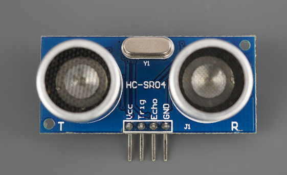
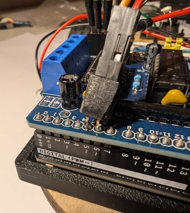
While the photoresistors are a rather simple sensor, the framework we have made will allow us to slot in another more complex sensor. We will use a ultrasonic distance sensor to follow a wall. Connect HC-SR04 with servo. Use double female header to access pins 5 and 6. Vcc → 5V, Trig → 5, Echo → 6, GND → GND.
Unfortunately, the motor shield blocks our access to the digital PWM pins which we need for this sensor. Its not elegant, but we can solder a double female header to the back pins. UNPOWER YOUR SYSTEM. Have an instuctor help you do this to pins 5 and 6. Then, plug the HC-SR04 Vcc, Trig, Echo, GND into 5v, pin 5, pin 6, and GND respectively.
Checkoff 4: Verify wiring of ultrasonic sensor with your instructors.
Part 5: Using the Ultrasound
This is a very common sensor and there are many tutorials of how to use it online. You will rarely know exactly how to program a sensor from memory. Use the internet to make/find a function called measureDistance() that returns an integer of the distance from the ultrasonic sensor. Then, upload the following code and move your hand in front of the ultrasonic sensor and make sure it responds as you expect.
// Pin assignments for HC-SR04
const int trigPin = 5;  // Trigger pin
const int echoPin = 6; // Echo pin

void setup() {
    Serial.begin(9600); // Initialize Serial Monitor

    // Set up HC-SR04 pins
    pinMode(trigPin, OUTPUT);
    pinMode(echoPin, INPUT);
}

void loop() {
    // Measure distance using HC-SR04
    int distance = measureDistance();

    Serial.print("Distance: ");
    Serial.print(distance);

    delay(20);
Checkoff 5: Ask your instructor for a check-off on completing Part (5). Show the ultrasound working..
Part 6: Wall Following
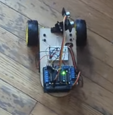
Now we can use this function and our proportional controller to track a wall. Angle your ultrasonic sensor at about 80degrees from straight forward (pointing mostly left). It is important that it is not at 90 degrees. (Mirror of the image below). The following code follows a right wall. Alter it and tune the proportional constants to follow a left wall.
#include

// Motors
AF_DCMotor motorLeft(1);   // M1
AF_DCMotor motorRight(4);  // M2

// Ultrasonic pins
const int trigPin = 5;
const int echoPin = 6;

void setup() {
  Serial.begin(9600);

  pinMode(trigPin, OUTPUT);
  pinMode(echoPin, INPUT);

  motorLeft.setSpeed(150);
  motorRight.setSpeed(150);
}

long getDistance() {
  digitalWrite(trigPin, LOW);
  delayMicroseconds(2);

  digitalWrite(trigPin, HIGH);
  delayMicroseconds(10);

  digitalWrite(trigPin, LOW);

  long duration = pulseIn(echoPin, HIGH);
  long distance = duration * 0.034 / 2; // cm
  return distance;
}

void moveForward() {
  motorLeft.run(FORWARD);
  motorRight.run(FORWARD);
}

void stopMotors() {
  motorLeft.run(RELEASE);
  motorRight.run(RELEASE);
}

void loop() {
  long distance = getDistance();

  Serial.print("Distance = ");
  Serial.println(distance);

  if (distance < 20 && distance > 0) {
    stopMotors();
  } else {
    moveForward();
  }

  delay(100);
}
Checkoff 6:Ask your instructor for a check-off on completing Part (6) Wall Following.
Part 7: Remix Sensor
Now that know how to write code for a given sensor, pick a sensor/output that you think will be useful for your project and make it work. This could be spinning a stepper motor, using a temperature or color sensor, or even the IMU. If you are unsure of a direction, ask your instructor for suggestions. Below is a list of inputs and outputs you can use.
- Color sensor
- IR transmitter & receiver
- IMU
- Temperature sensor
- LCD/OLED
- Servo motor
- Stepper motor
Checkoff 7: Verify implementation of your chosen sensor/output.