Introduction & Safety
3D printing is an additive manufacturing process. You will learn advanced modeling, assembly, and fabrication skills. Follow all safety instructions while using machines and tools.
- Learn advanced 3D modeling Techniques (Revolve, Sweep, Warp).
- Design for Multimaterial 3D Printing.
- CAD a simple rotating element around a shaft.
- CAD a threaded object.
- Make a Mechanical Assembly.
- Render a 3D Model in Fusion360.
- Export files and prepare them for 3D printing.
Fabrication Quest of the Day:
- Assemble your Rotating Keychain.
- Post-process your 3D print.
Software & Hardware
- Software: Fusion360
- Machines: 3D Printer
Part 1: Creating Variables & Equations for Dynamic Dimensioning!
(10 minutes)
Video Summary: Dimensioning models through variables allows for model dimension modification with ease. To create dimension variables go to: Modify → Change Parameters → Add User Parameter (top "+" sign). Create a variable for “shaft_outer_d” representing the inner diameter of the Threaded Shaft, and set it to 9mm. Follow the table below to add all the variables and one equation to your Fusion File Parameters. Save as you go!
| # | Part Name (do not add to Fusion) | Variable Name (add in Fusion) | Expression | Unit |
|---|---|---|---|---|
| 2 | Shaft Outer Diameter | shaft_outer_d | 9 | mm |
| 3 | Shaft Length for 3 Rotating Blocks | shaft_length_3b | 36.2 | mm |
| 4 | Shaft Length for 4 Rotating Blocks | shaft_length_4b | 48.2 | mm |
| 5 | Shaft Threaded Hole Depth | thread_depth | 10 | mm |
| 7 | Keychain Hole Diameter | keychain_hole_d | 4 | mm |
| 9 | Rotating Block Size | rot_b_size | 12 | mm |
| 10 | Rotating Block Thickness | rot_b_thick | 12 | mm |
| 11 | Rotating Block Hole Tolerance | tolerance | 0.6 | mm |
| 12 | Rotating Block Hole Diameter | rot_b_hole_d | shaft_outer_d + tolerance | mm |
Checkoff 1: Ask your instructor for a check-off on completing Part (1).
Part 2: Sketch and Dimension Parametrically
(Sketching Keychain Shaft, 5 minutes)
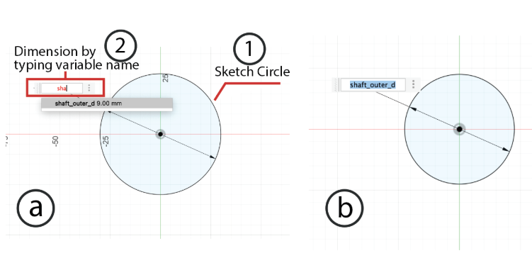
- Draw a circle at the center (0,0).
- Dimension the first circle with “shaft_outer_d”.
- Exit Sketch, and rename the Sketch to "shaft-circle".
Part 3: Extruding the Sketch
(Give height to the shaft, 5 minutes)
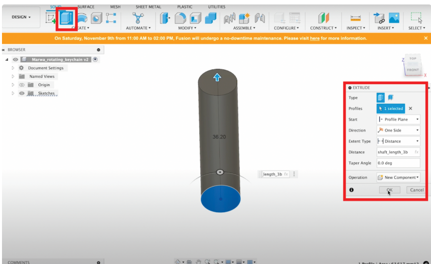
- Click on Create.
- Select the Extrude Tool.
- Under Profile, select the area formed by the circle from your "shaft-circle" sketch.
- Set Direction to One Side.
- Type Distance as “shaft_length_3b” or "shaft_length_4b".
- Choose operation as New Component.
- Right click component and rename it "Shaft".
Part 4: Making a Threaded Hole
(7 minutes)
- Toggle "Shaft-circle" sketch back on.
- Go to Create > Hole Tool.
- Under Face, select top face of the cylinder.
- Set Hole Type to “Simple”, Tap Type “Tapped”, Thread Offset “Full”, Drill Point “Angle”.
- Depth: "thread_depth", Size: 7mm, Designation: M7mmx1mm.
- Have Modeled checked ON, click OK.
Checkoff 2: Show your shaft with threaded hole to your instructor.
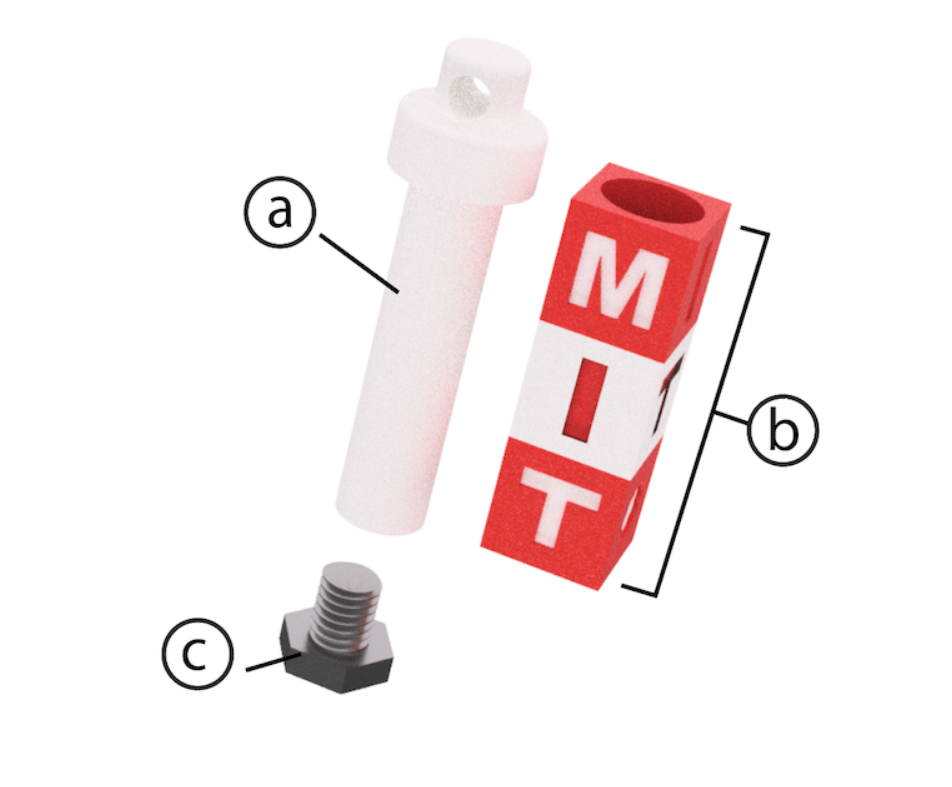
Part 5: Creating Profile of Keychain Holder Head (Remix Optional)
(20 minutes)
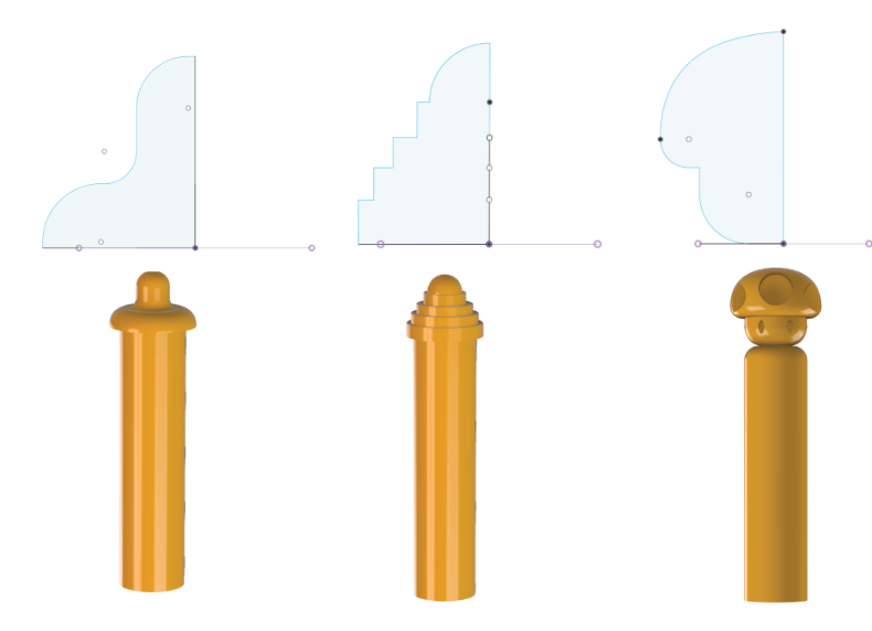
- Create Axis Through Cylinder (Construct → Axis Through Cylinder).
- Create Plane at Angle (Construct → Plane at Angle → 0°).
- Create new sketch on plane.
- Project top circle perimeter and sketch top holder profile.
- Finish sketch.
Checkoff 3: Show & explain your sketched profile to your instructor.
Part 6: Revolving Radially Symmetric Geometry
(5 minutes)
- Create > Revolve.
- Select profile and axis of symmetry.
- Set angle 360°.
- Click OK.
Part 7: Making Hole for Keychain
(5 minutes)
- Create tangent plane.
- Sketch circle where hole should be.
- Dimension circle (4mm).
- Extrude cut circle, symmetric direction.
Checkoff 4: Show your shaft's keychain hole to your instructor.
Part 8: Understanding Sketch Relationships & Constraints
(5 minutes)
Part 9 (Optional): Wrapping/Embossing a Design on Your Cylindrical Shaft
(5 minutes)
- Profile: Select sketch to emboss.
- Face: Select curved/flat surface.
- Emboss Type: Add/Raise or Deboss/Cut.
- Depth: Set height/depth.